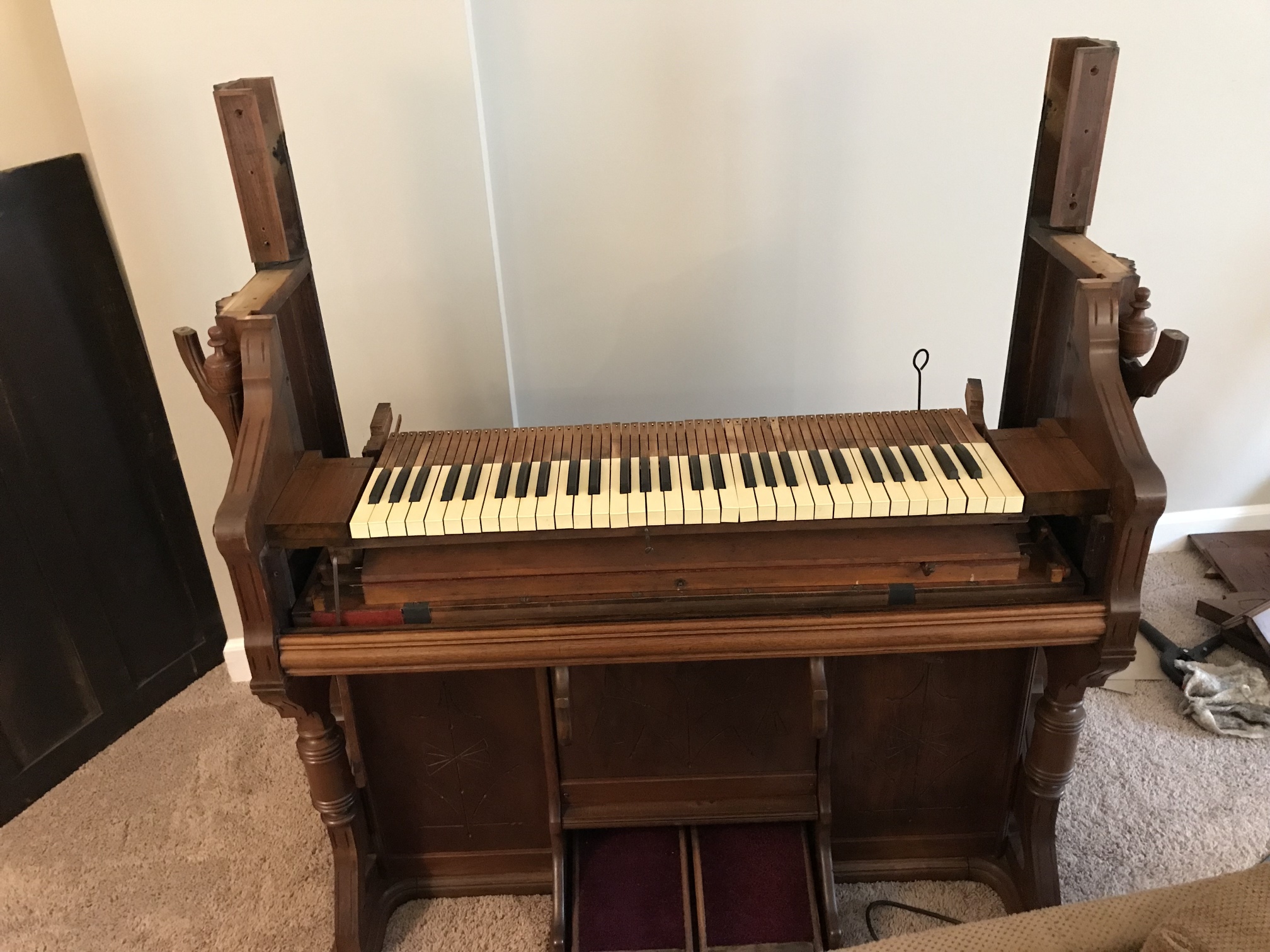
Actually, there isn’t much to say about the keyboard. Everything pretty much went according to plan, mostly because they just needed cleaning. A real pro would have replaced the bushings, polished the tops, repainted any fading sharps, straightened warped keys, then re-leveled the whole thing. But, when you think about it, the yellowed celluloid reveals the organ’s heritage. The warped keys give it character. And a little unevenness is only natural. You gotta keep the big picture in mind here.
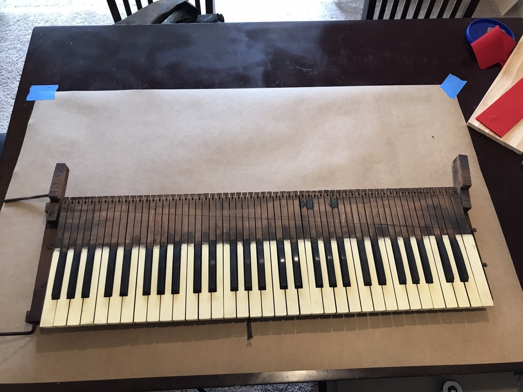
After vacuuming, the keys were still pretty dirty.
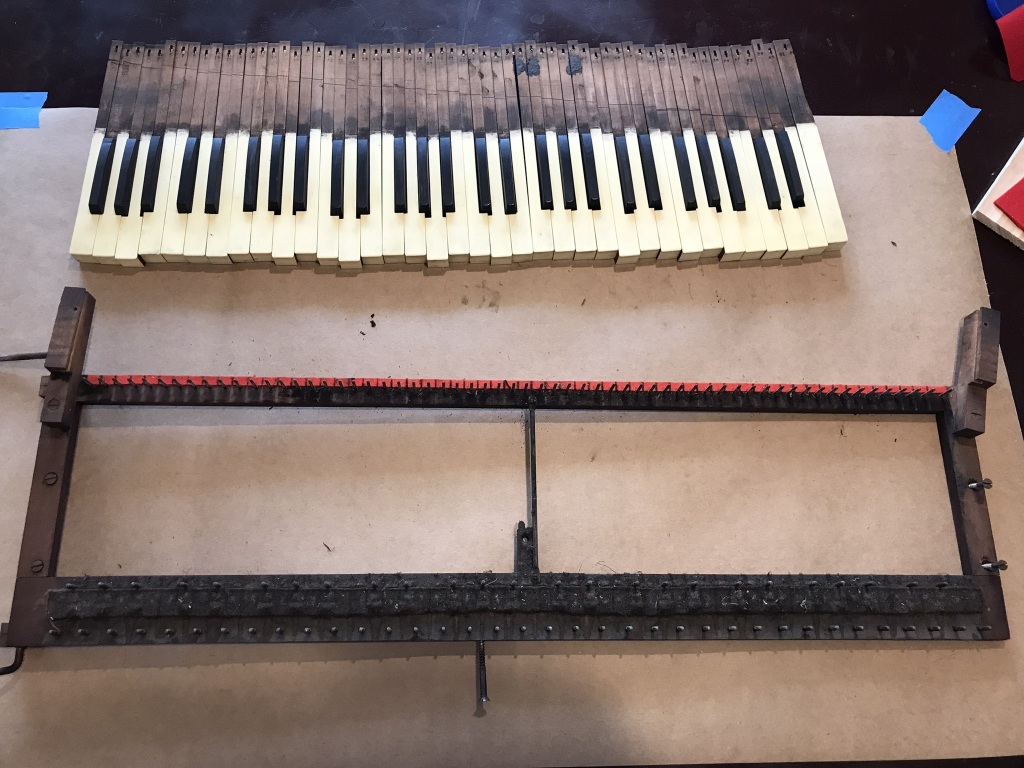
But not as bad as the bit under the keys!
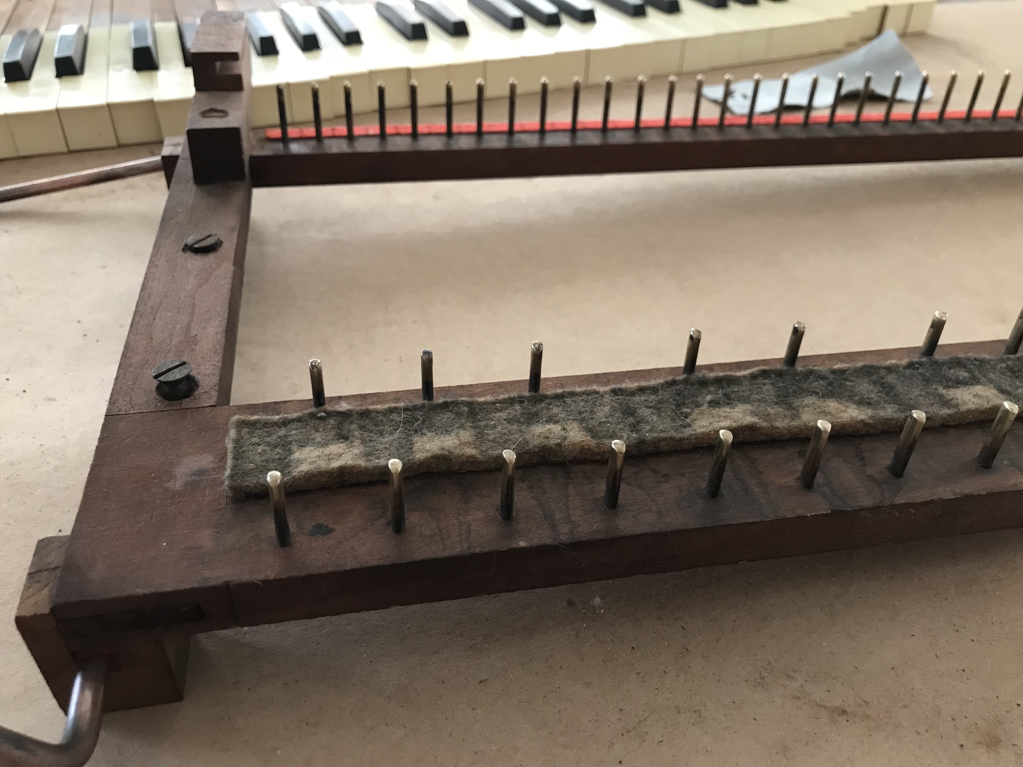
After vacuuming and polishing. The felt is dirty, but still usable.
In the last post, I mentioned that I wanted to improve the stop action. This was the first major component I’d restored, and I figured I could avoid some earlier mistakes. So I repainted and polished the stop rods, replaced the key felt, replaced some bushings, and straightened some knobs. While testing the stop linkages, though, something seemed wrong. The two rightmost and leftmost stops didn’t seem to activate all the way, leaving some keys silent even when completely pulled out. Checking my pictures, I realized—I’d mixed up the stop rods.
This was pretty frustrating, since I’d tried to avoid mixing anything up. Worse, the eleven rods were fairly similar, differing only in the length and placement of a slit down the middle. I wasn’t facing the full 40 million permutations—since, using some common sense and photos, you could narrow to which stop a rod belonged to two or three options—but that still left a lot of possibilities.
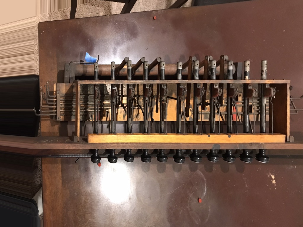
But I had one hope. I had a clear image of the stops before I started restoration. It was photographed not exactly from above, but if I could re-project the image to remove the distortions, measuring various features on the stops should reveal the original order. Having something similar for a past project, I knew just the tool.
$ magick \
    original.jpeg \
    -distort Perspective '266,277 267,277 976,308 976,277 266,479 266,479 967,441 976,479' \
    working.jpeg
At this point, you can calculate a pixel-to-inches conversion factor for the horizontal and vertical axis, and then determine the sizes of various features on each stop rod. A small JavaScript program made that much less tedious. Then, with my pair of calipers, I carefully measured the same features on each of my physical stop rods.
The original image. The stops are very visible, but the foreshortening is too severe to be for it to be very useful.
Reprojected! It looks funky, but the rods are now more or less the same size. It’s not perfect, and the horizontal axis is compressed a bit, but that’ll all come out in the wash.
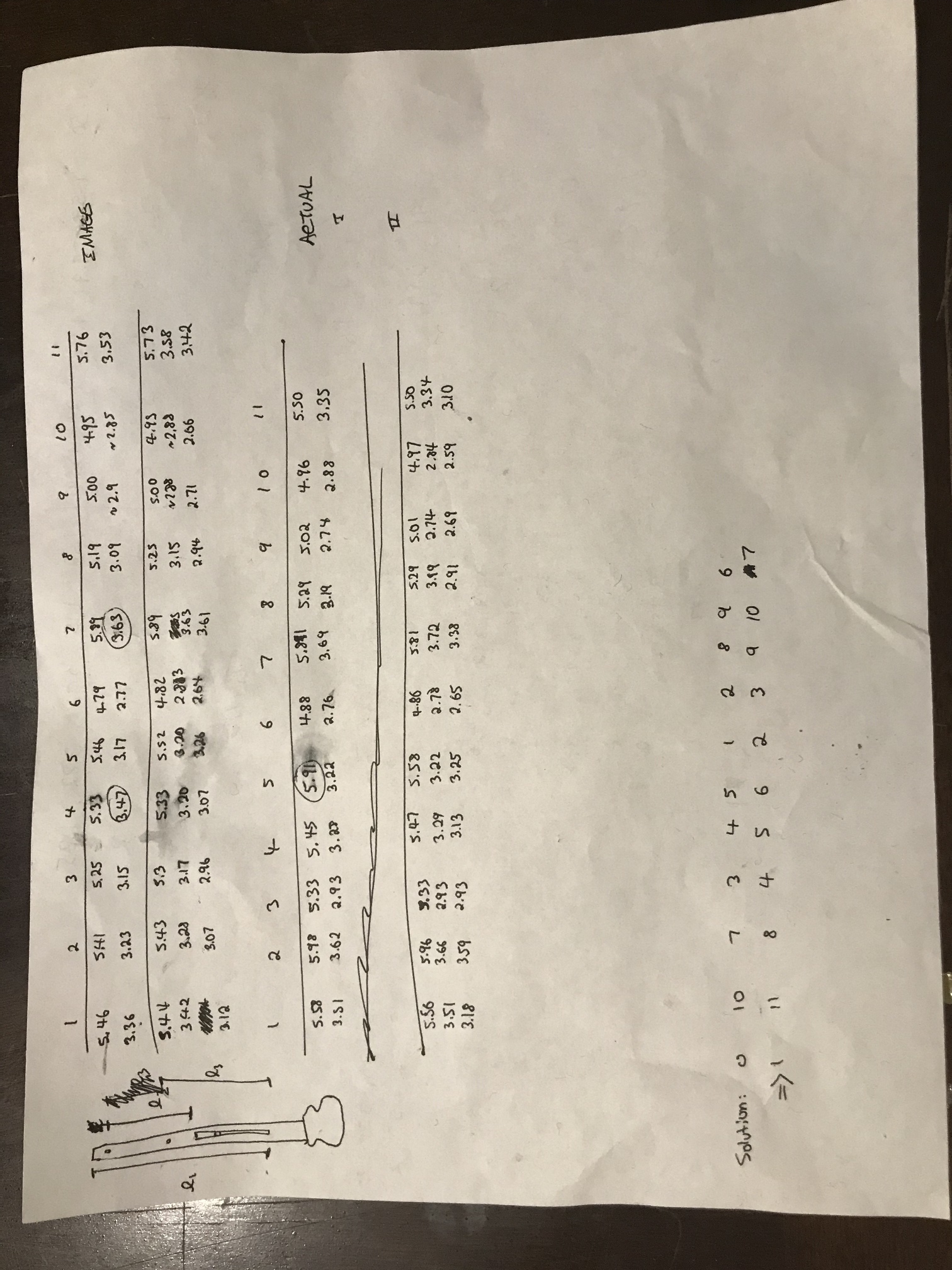
My measurements (and on the bottom, the calculated matching). I measured everything twice, which was good, because I found some mistakes the second time.
I was hoping to see a nice, clean correspondence between the photograph and physical measurements, but it wasn’t that easy. To reduce error, I measured three independent features on each stop rod, and it’s a lot harder to correlate three numbers than one. But I had one more trick up my sleeve.
I’m a programmer! So I entered all my measurements into my computer and wrote a tiny genetic optimizer to find the best ordering of stop rods. Since there were only 11! = 40 million possible permutations, I could have just found the best one through brute force, but that didn’t occur to me at the time. The idea was, start with a random ordering of the stop rods. Then create a hundred or so new orderings that differ from the base ordering only in that two elements have been swapped. Compare each ordering to the photograph, and choose the best one. Repeat this a few thousand times, and you have a pretty good chance of finding the best ordering. This is still a lot of work, but computers are a lot of fast.
I haven’t included my program, because that sort of thing is dry reading, even for programmers. (Though if you’re curious or would find it useful, send me an email, I’d be happy to give it to you.) Suffice to say, it ran very quickly and produced the same solution every time. At least once I tuned my fitness function (difference squared + some weighting + some noise), genetic algorithms are very dependent on that. In the end, when I put the stop rods in the specified order, they worked!
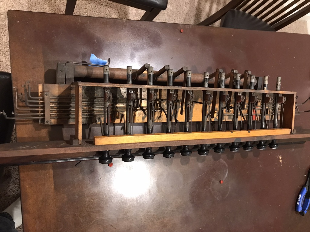
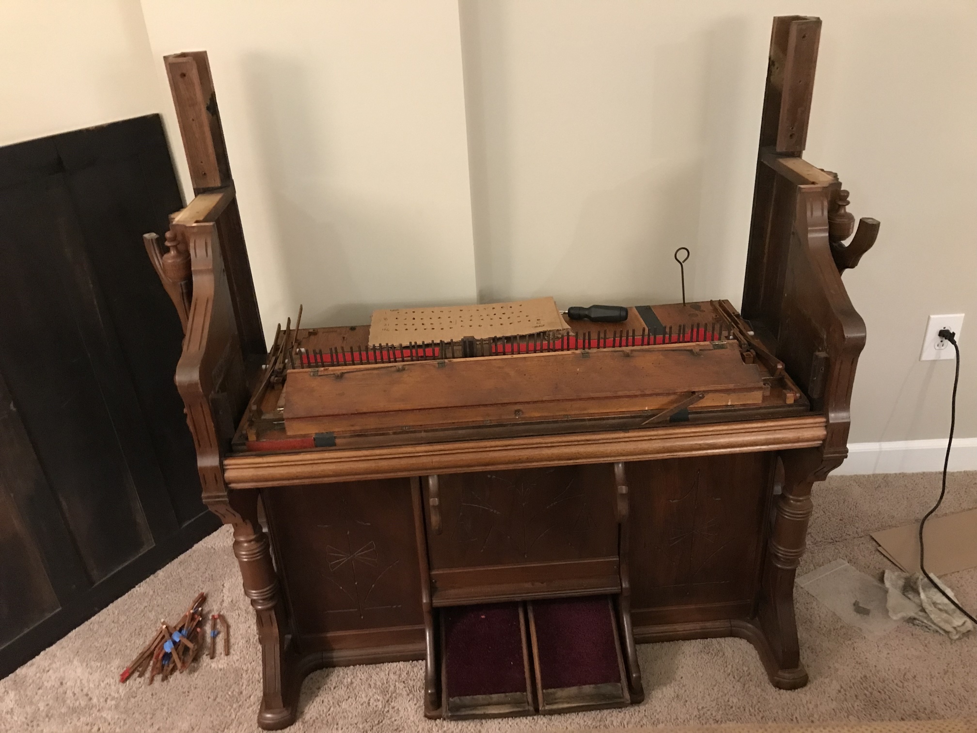
At this point, all that really remained was reassembly. I took this part carefully, spreading it out over a few days.
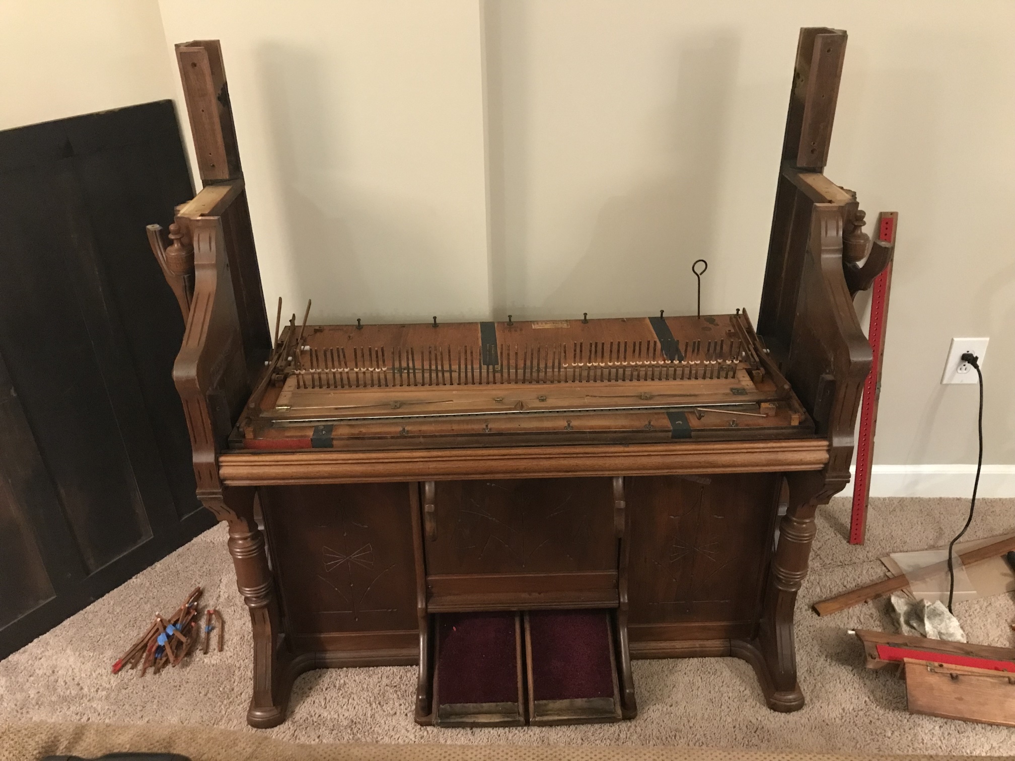
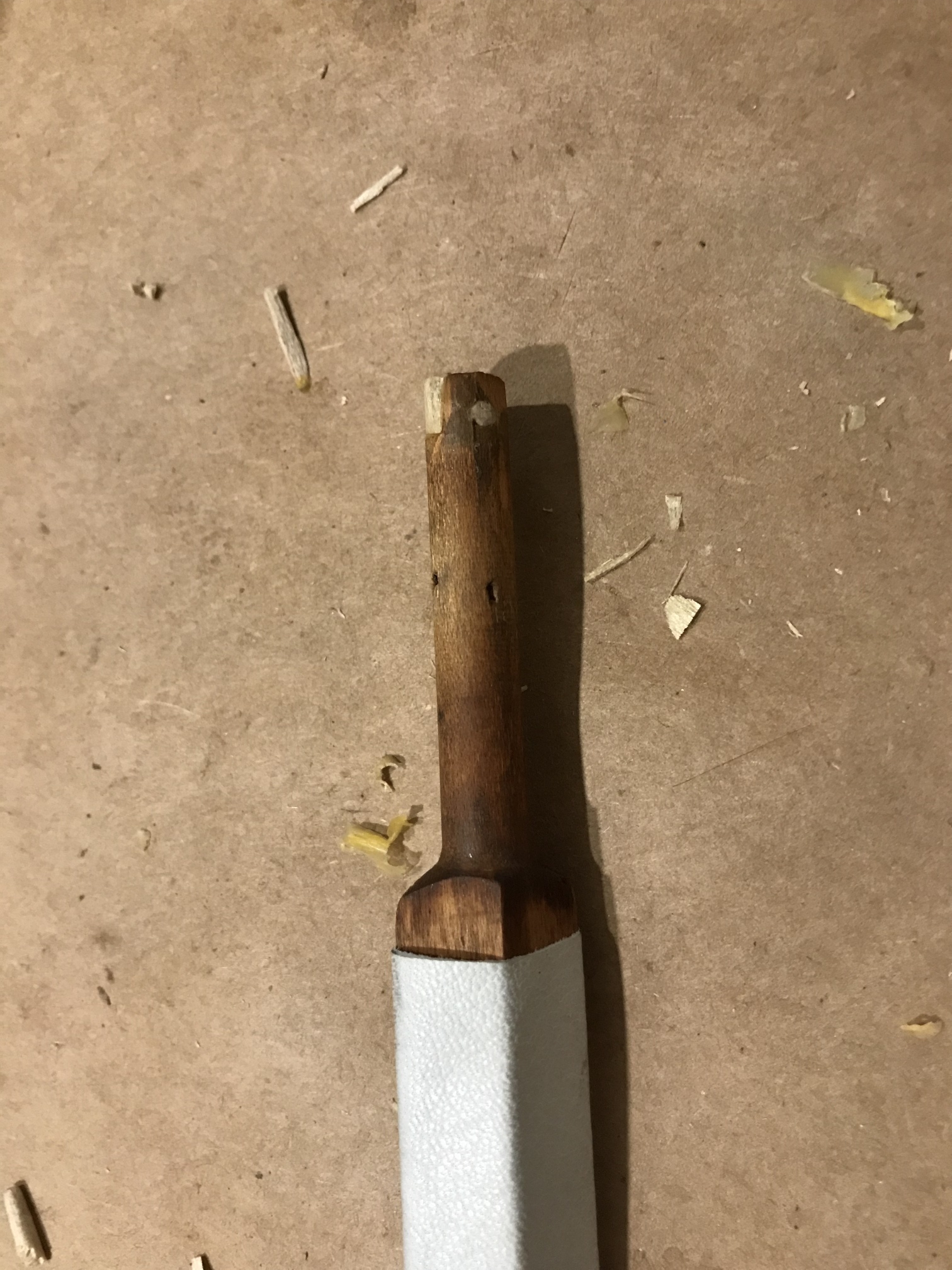
Shortly after taking this picture, I accidentally snapped three pitmans. I was worried I might have to replace them, but some wood glue was enough.
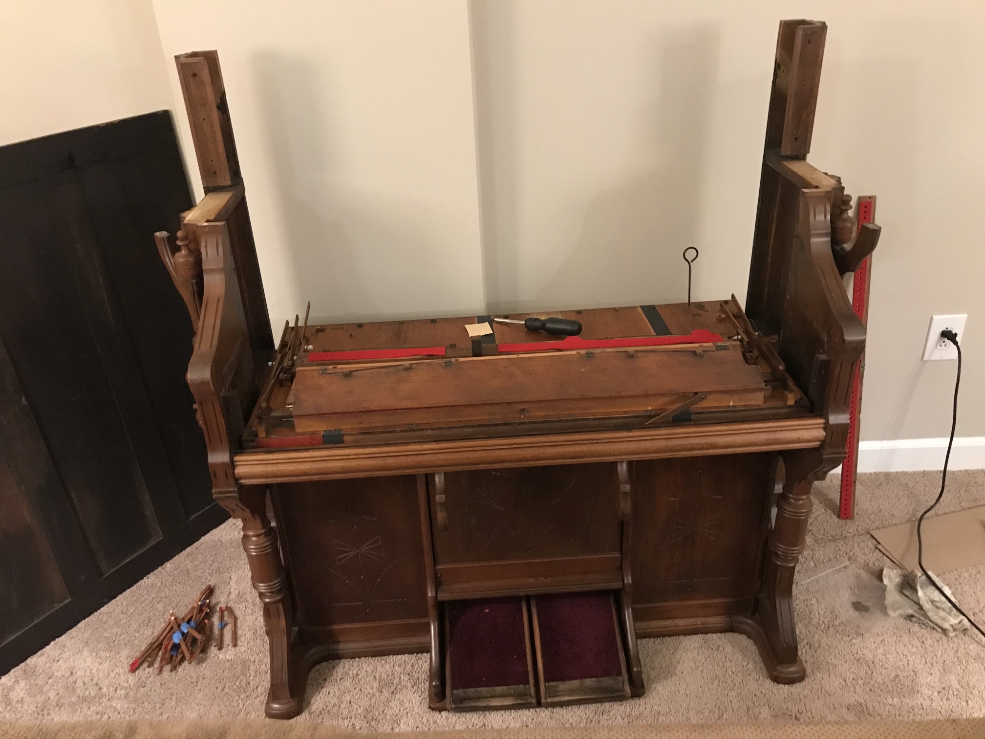
Swell covers installed. I took the pitmans back out to avoid breaking any more.
Pitmans repaired, lubricated with dry graphite, and re-installed.
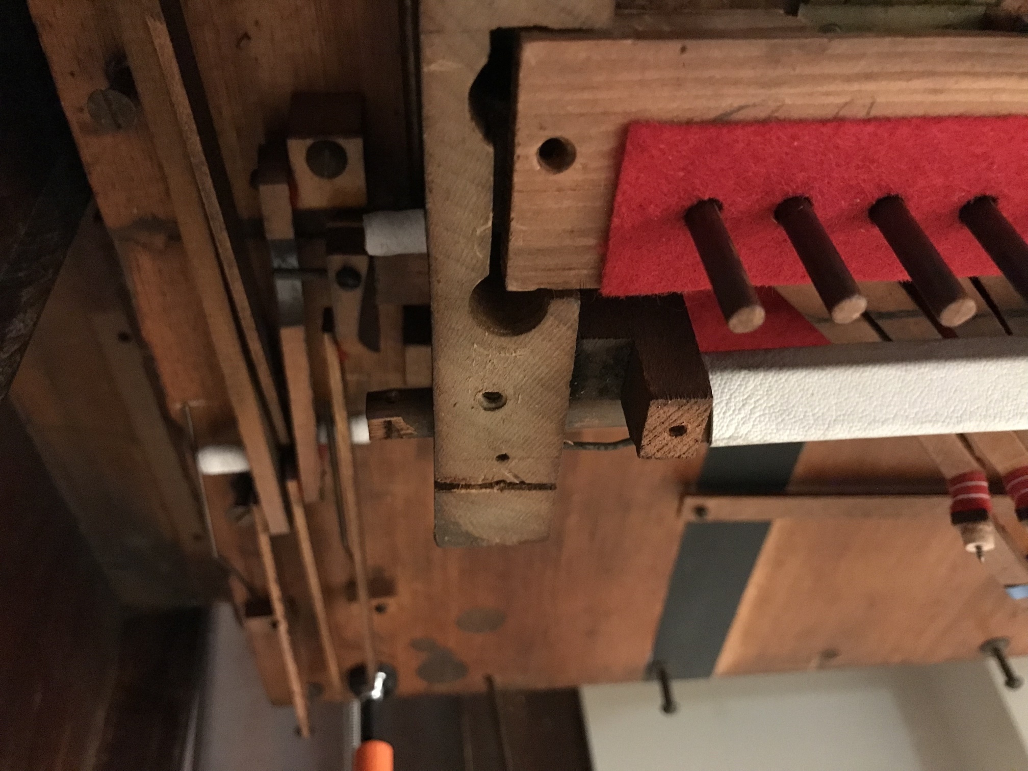
While doing a sort of dry run, I discovered that the treble couple wasn’t fully engaging. Upon futher testing, the set screw broke free, breaking the coupler.
The patched coupler. Better than new, since the redrilled hole is properly centered, ensuring that the coupler engages properly.
Newly-repaired coupler action lubricated and installed.
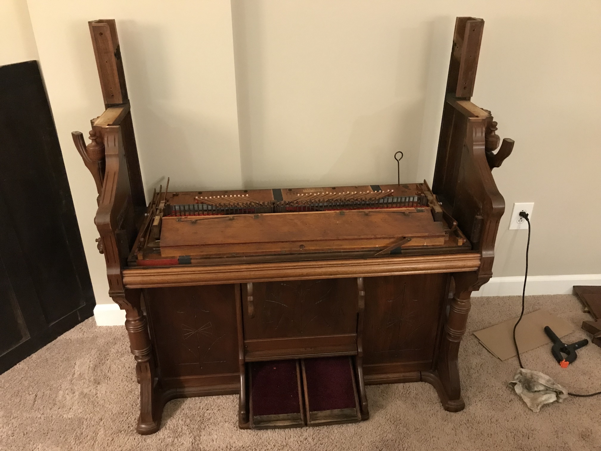
Keyboard and key cheeks installed.
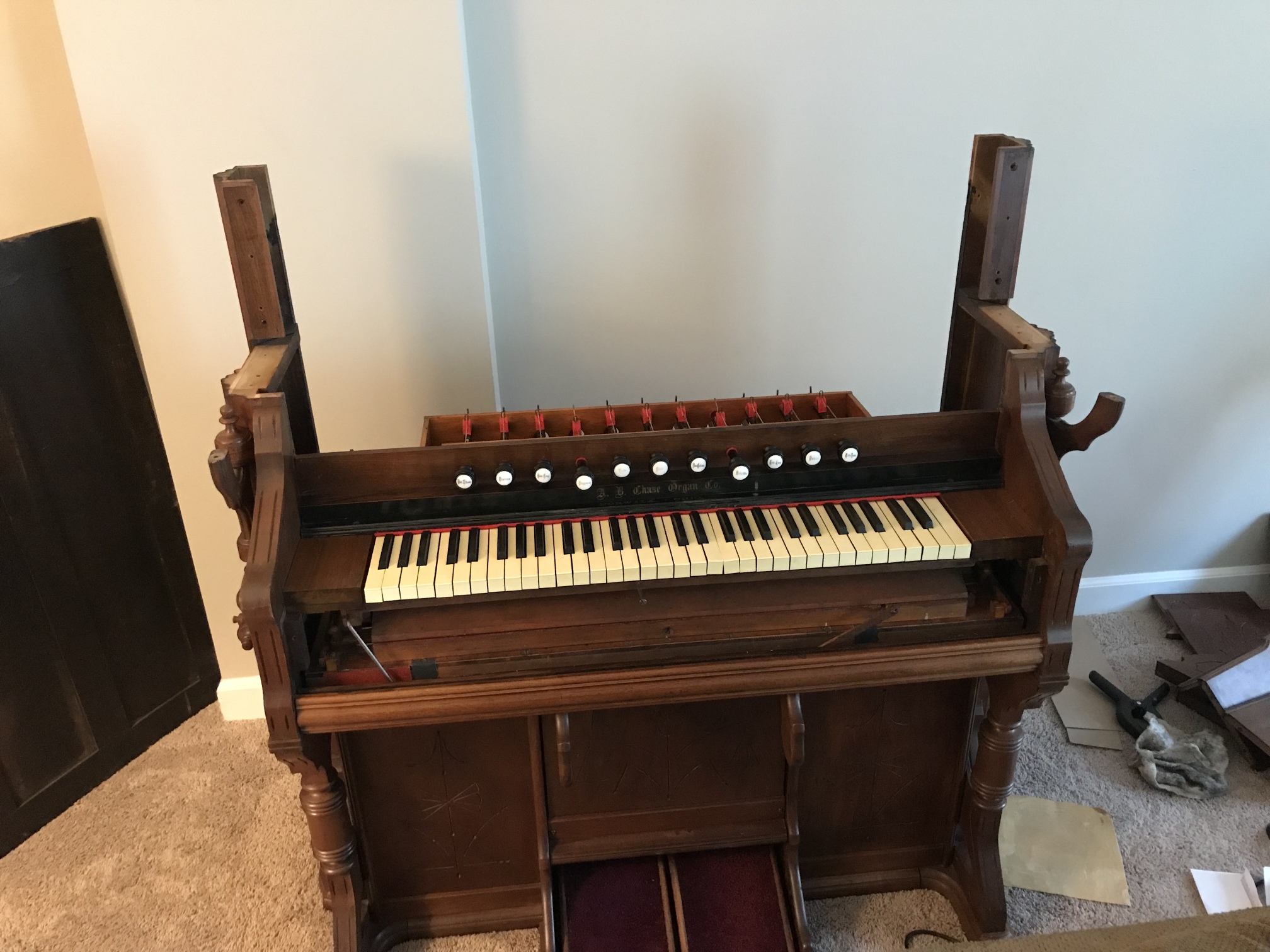
Stop action installed. Keen-eyed readers will note that the key felt is a bit too wide, I replaced it with thicker, darker, and better-cut felt a few days later.
At this point, the organ was completely playable. I decided to delay the full reassembly, though, figuring that if something was going to break, it’d be far easier to fix if I didn’t have to disassemble the entire case.